請參考連結 : http://www.esp8266.com/wiki/doku.php?id=esp8266-test-boards
2015年8月30日 星期日

NodeMcu Devkit 0.9/1.0 開發版差異
資料來源 : NodeMCU GitHub
主要差異:
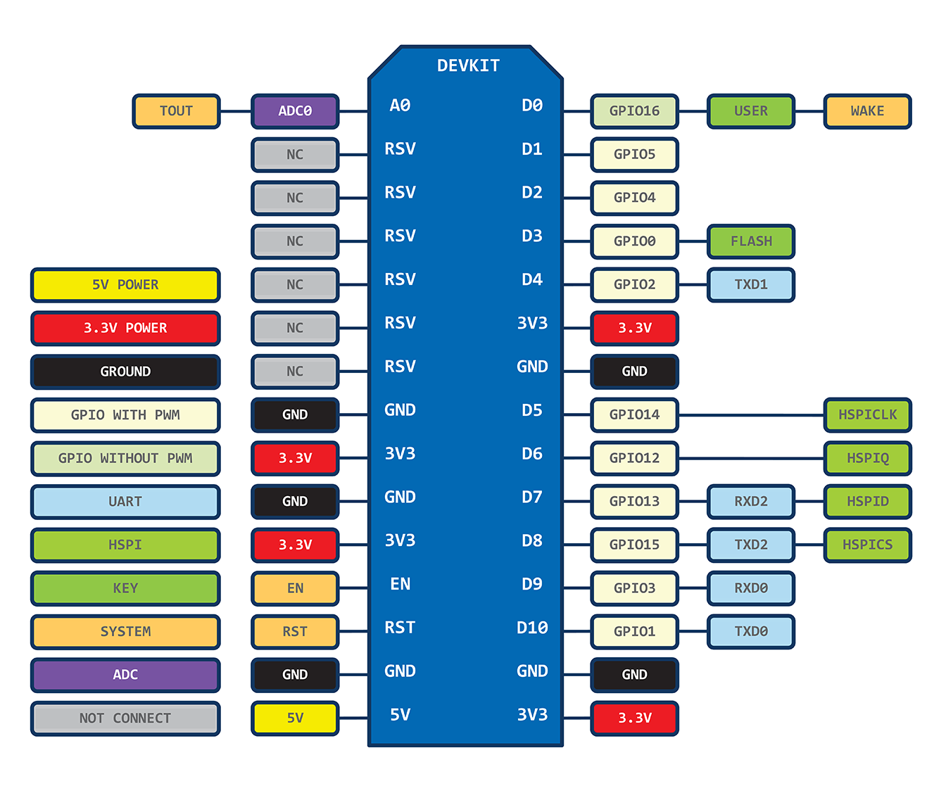
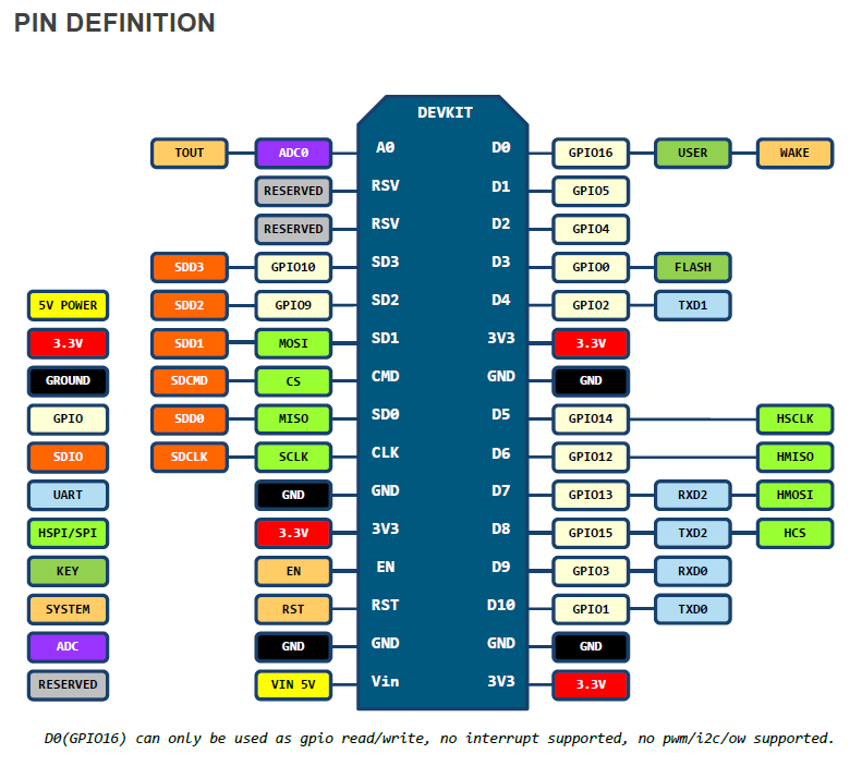
Devkit 0.9與1.0腳位定義有差異,主因是因為ESP-12E多了6支引腳
NodeMcu Devkit 1.0 = ESP-12E + CP2102
NodeMcu Devkit 0.9 = ESP-12 + CH340G
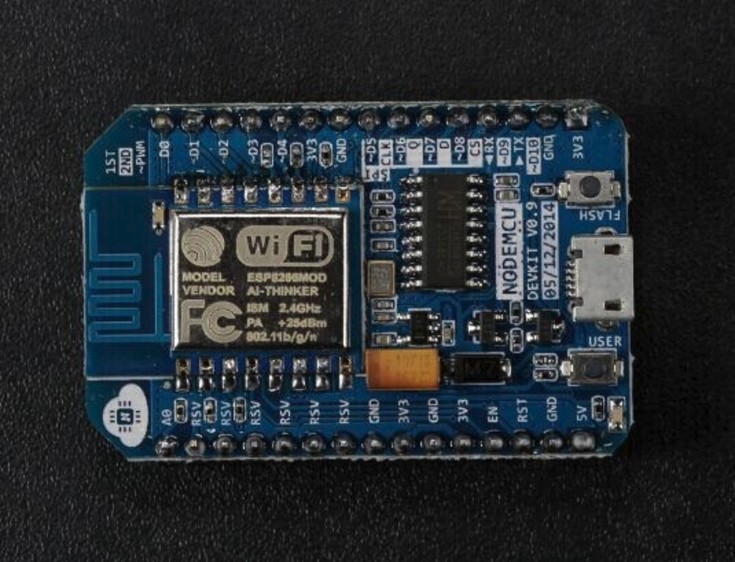
外觀比較:
NodeMcu Devkit 0.9
 NodeMcu Devkit 1.0
腳位比較
主要差異在於ESP-12E 多引出了6根腳,所以Devkit 1.0 也跟著引出這6根腳位NodeMcu Devkit 0.9
NodeMcu Devkit 1.0
2015年4月9日 星期四
NodeMCU - NTP Client
今天想到要利用NTP Server 來 Sync 時間 , 搜尋了一下,找到了這個連結 ........
ntp.lua 內容如下:
-- -----------------------------------------------------------------------------------
-- for a continuous run:
-- TIME=loadfile("ntp.lua")()
-- TIME:run(timer,updateinterval,syncinterval,[ntp-server])
-- TIME.hour TIME.minute TIME.second are updated every 'updateinterval'-seconds
-- NTP-server is queried every 'syncinterval'-seconds
--
-- a one-time run:
-- ntprun=loadfile("ntp.lua")
-- ntprun():sync(function(T) print(T:show_time()) end)
--
-- config:
-- choose a timer for udptimer
-- choose a timeout for udptimeout
--    timer-function to close connection is needed - memory leaks on unanswered sends :(
-- set tz according to your timezoneddddddd
-- choose a NTP-server near you and don't stress them with a low syncinterval :)
-- -----------------------------------------------------------------------------------

return({
    hour=0,
    minute=0,
    second=0,
    lastsync=0,
    ustamp=0,
    tz=8,
    udptimer=2,
    udptimeout=1000,
    ntpserver="193.170.62.252",
    sk=nil,
    sync=function(self,callback)
        -- print("SYNC " .. self.ustamp .. " " .. self.ntpserver)
        -- request string blindly taken from http://arduino.cc/en/Tutorial/UdpNTPClient ;)
        local request=string.char( 227, 0, 6, 236, 0,0,0,0,0,0,0,0, 49, 78, 49, 52,
        0,0,0,0,0,0,0,0,0,0,0,0,0,0,0,0,0,0,0,0,0,0,0,0,0,0,0,0,0,0,0,0
        )
        self.sk=net.createConnection(net.UDP, 0)
        self.sk:on("receive",function(sck,payload)
            -- tmr.stop(self.udptimer)
            sck:close()
            self.lastsync=self:calc_stamp(payload:sub(41,44))
            self:set_time()
            if callback and type(callback) == "function" then
                callback(self)
            end
            collectgarbage() collectgarbage()
            -- print("DONE " .. self.ustamp)
        end)
        self.sk:connect(123,self.ntpserver)
        tmr.alarm(self.udptimer,self.udptimeout,0,function() self.sk:close() end)
        self.sk:send(request)
    end,
    calc_stamp=function(self,bytes)
        local highw,loww,ntpstamp
        highw = bytes:byte(1) * 256 + bytes:byte(2)
        loww = bytes:byte(3) * 256 + bytes:byte(4)
        ntpstamp=( highw * 65536 + loww ) + ( self.tz * 3600)    -- NTP-stamp, seconds since 1.1.1900
        self.ustamp=ntpstamp - 1104494400 - 1104494400         -- UNIX-timestamp, seconds since 1.1.1970
        -- print(string.format("NTP: %u",ntpstamp))
        -- print(string.format("UIX: %u",self.ustamp))
        return(self.ustamp)
    end,
    set_time=function(self)
        self.hour = self.ustamp % 86400 / 3600
        self.minute = self.ustamp % 3600 / 60
        self.second = self.ustamp % 60
        -- print(string.format("%02u:%02u:%02u",hour,minute,second))
    end,
    show_time=function(self)
        return(string.format("%02u:%02u:%02u",self.hour,self.minute,self.second))
    end,
    run=function(self,t,uinterval,sinterval,server)
        if server then self.ntpserver = server end
        self.lastsync = sinterval * 2 * -1    -- force sync on first run
        tmr.alarm(t,uinterval * 1000,1,function()
            self.ustamp = self.ustamp + uinterval
            self:set_time()
            -- print(self:show_time())
            if self.lastsync + sinterval < self.ustamp then
                self:sync()
            end
        end)
    end
})
測試了一下,真的能用, 輸出如下:
> ntptable=loadfile("ntp.lua")()
> --調整時區設定, 在這我設成台北時間: GMT+8
> ntptable.tz=8
> --設定timerid=1 , 定時每1秒從"tock.stdtime.gov.tw"讀取NTP時間
> ntptable:run(1,1,0,"211.22.103.157")
> print(ntptable:show_time())
05:10:38
> print(ntptable:show_time())
05:11:20
or
> ntpfun=loadfile("ntp.lua")
> ntpfun():sync(function(T) print(T:show_time()) end)
> 05:15:59
ntpfun():sync(function(T) print(T:show_time()) end)
> 05:16:29
or
> ntptable=loadfile("ntp.lua")()
> ntptable:sync(function(T) print(T:show_time()) end)
> 05:15:59
ntptable:sync(function(T) print(T:show_time()) end)
> 05:16:29
註:別忘了要設時區,不然時間會有時差的....
另外,若有需要,可自行依當地時區,再進行日光節約時間校正 .....
以下為台灣國家時間與屏率標準實驗室NTP Server :
tock.stdtime.gov.tw  211.22.103.157
watch.stdtime.gov.tw  118.163.81.63
time.stdtime.gov.tw  118.163.81.61
clock.stdtime.gov.tw  211.22.103.158
tick.stdtime.gov.tw 118.163.81.62
相關參考資料:
鳥哥的Linux 私房菜-- NTP 時間伺服器
NTP 伺服器位址 - 國家時間與頻率標準實驗室
NTP - Wikipedia
夏令時間- 維基百科,自由的百科全書 - Wikipedia
2015年4月8日 星期三
NodeMCU - uploader and file module
file module
file.remove
file.open
file.close
file.readline
file.writeline
file.read
file.write
file.flush
file.seek
file.list
file.format
file.rename
nodemcu-uploader.py
A simple tool for uploading files to the filesystem of an ESP8266 running NodeMCU as well as some other useful commands.
Usage
--port and --baud are set to default /dev/ttyUSB0 and 9600 respectively.
mark@mark-laptop:~/nodemcu-uploader-master$ sudo ./nodemcu-uploader.py --port /dev/ttyUSB3 file format
Formating...
file.format()

mark@mark-laptop:~/nodemcu-uploader-master$ sudo ./nodemcu-uploader.py --port /dev/ttyUSB3 upload init.lua
Preparing esp for transfer.
Transfering init.lua as init.lua
All done!

mark@mark-laptop:~/nodemcu-uploader-master$ sudo ./nodemcu-uploader.py --port /dev/ttyUSB3 file list
Listing files
for key,value in pairs(file.list()) do print(key,value) end
init.lua    32
>

mark@mark-laptop:~/nodemcu-uploader-master$ sudo ./nodemcu-uploader.py --port /dev/ttyUSB3 download init.lua:new.lua
Transfering init.lua to new.lua
All done!
註: 燒錄新版 Firmware後 ,先前所放入的lua file會依然存在,不會被覆蓋,僅nodemcu firmware
被更新....
mark@mark-laptop:~/esptool$ sudo ./esptool.py --port /dev/ttyUSB0 read_mac
Connecting...
MAC: 18:fe:34:9e:99:29
mark@mark-laptop:~/esptool$ sudo ./esptool.py --port /dev/ttyUSB0 flash_id
Connecting...
Manufacturer: ef
Device: 4016
2015年4月1日 星期三
NodeMCU固件- node/wifi/net/uart module
參考連結: NodeMCU API指令
node module
node.led --deprecated
node.key --deprecated
node.readvdd33 --deprecated
node.input
node.output
node.compile
node.info
node.chipid
node.flashid
node.heap
node.restart
> print(node.info())
0 9 6 10492404 1458415 4096 2 40000000
==>SDK Version : 0.9.6
==>chipid : 10492494
==>flashid:1458415 (0x1640EF) 0xEF代表Winbond , 0x4016對應32Mbits
==>flashsize=4096 KBytes
==>flashmode=2 (DIO)
==>flashspeed=40000000 (40MHz)
http://code.coreboot.org/svn/flashrom/trunk/flashchips.h
> print(node.heap())
34288
>
==>剩餘可用memory : 34288 Bytes
wifi module
wifi.getmode
wifi.setmode
wifi.startsmart
wifi.stopsmart
wifi.sleeptype
wifi.sta module
node.output
node.compile
node.info
node.chipid
node.flashid
node.heap
node.restart
> print(node.info())
0 9 6 10492404 1458415 4096 2 40000000
==>SDK Version : 0.9.6
==>chipid : 10492494
==>flashid:1458415 (0x1640EF) 0xEF代表Winbond , 0x4016對應32Mbits
==>flashsize=4096 KBytes
==>flashmode=2 (DIO)
==>flashspeed=40000000 (40MHz)
http://code.coreboot.org/svn/flashrom/trunk/flashchips.h
::1458400 (0x1640E0) => 32Mbits
::1458415 (0x1640EF) => 32Mbits
#define WINBOND_NEX_ID 0xEF /* Winbond (ex Nexcom) serial flashes */
#define WINBOND_NEX_W25Q32_V 0x4016 /* W25Q32BV; W25Q32FV in SPI mode (default) */
::1327343 (0x1440EF) => 8Mbits
#define WINBOND_NEX_W25Q80_V 0x4014 /* W25Q80BV */
::1261768 (0x1340C8) => 4Mbits
#define GIGADEVICE_ID 0xC8 /* GigaDevice */
#define GIGADEVICE_GD25Q40 0x4013 /* Same as GD25QB */
> print(node.heap())
34288
>
==>剩餘可用memory : 34288 Bytes
wifi module
wifi.getmode
wifi.setmode
wifi.startsmart
wifi.stopsmart
wifi.sleeptype
wifi.sta module
wifi.sta.config
wifi.sta.connect
wifi.sta.disconnect
wifi.sta.autoconnect
wifi.sta.getip
wifi.sta.getmac
wifi.sta.setip
wifi.sta.getap : scan and get AP list
wifi.sta.status
wifi.stat.getbroadcast
wif.iap module
wifi.ap.config
wifi.ap.getip
wifi.ap.setip
wifi.ap.getmac
wifi.ap.setmac
wifi.ap.getbroadcast
uart module
baud = 300, 600, 1200, 2400, 4800, 9600, 19200, 38400, 57600, 74880, 115200, 230400, 460800, 921600, 1843200, 2686400.
心得: Baud Rate可以儘量設高點,太低有時Lua command出錯"
> print("Heap=".. node.heap())
tmr.delay(1000)
print(no>> de.info())
stdin:2: ')' expected (to close '(' at line 1) near 'de'
由上看出,若輸出不夠快則輸入值會影響輸輸入,此應該是Lua的Bug吧!!!!!????(待查證)
註: 各廠USB-Serial不見得支援所有Baud Rate, 例如PL2303 在Ubuntu12.04下不支援 1843200 及2686400,不知是硬體還是軟體限制?
補充: 同樣Ubuntu環境用FT232RL可設達2686400, 貴一點還是值得的......
補充: 同樣Ubuntu環境用CH341不支援 1843200 及2686400
setup uart in init.lua
>print(uart.setup(0,921600,8,0,1,1))
921600
wifi.sta.connect
wifi.sta.disconnect
wifi.sta.autoconnect
wifi.sta.getip
wifi.sta.getmac
wifi.sta.setip
wifi.sta.getap : scan and get AP list
wifi.sta.status
wifi.stat.getbroadcast
wif.iap module
wifi.ap.config
wifi.ap.getip
wifi.ap.setip
wifi.ap.getmac
wifi.ap.setmac
wifi.ap.getbroadcast
uart module
baud = 300, 600, 1200, 2400, 4800, 9600, 19200, 38400, 57600, 74880, 115200, 230400, 460800, 921600, 1843200, 2686400.
註: 各廠USB-Serial不見得支援所有Baud Rate, 例如PL2303 在Ubuntu12.04下不支援 1843200 及2686400,不知是硬體
補充: 同樣Ubuntu環境用FT232RL可設達2686400, 貴一點還是值得的......
補充: 同樣Ubuntu環境用CH341不支援 1843200 及2686400
setup uart in init.lua
>print(uart.setup(0,921600,8,0,1,1))
921600
uart.setup
uart.on
uart.write
uart.on
uart.write
https://github.com/nodemcu/nodemcu-firmware/issues/15
https://github.com/nodemcu/nodemcu-firmware/issues/57
等待資料接收,最大可設255 Bytes, 下面範例為接收4個bytes
uart.on("data", 4,
      function(data)
        print("receive from uart:", data)
        if data=="quit" then
          uart.on("data")
        end
    end, 0)
    -- when '\r' is received.
    uart.on("data", "\r",
      function(data)
        print("receive from uart:", data)
        if data=="quit\r" then
          uart.on("data")
        end
    end, 0)
net module
net.createServer
net.createConnection
net.server module
net.server:listen
net.server.stop
net.socket module
net.socket:connect
net.socket.send
net.socket.on
net.socket.close
net.socket.dns
----------------------------------------------------------------------------------------------------------------
>wifi.setmode(wifi.SOFTAP)
>print(wifi.getmode())
2
>print(node.chipid())
10393897
>print("ESP_"..string.format("%X",node.chipid()))
ESP_9E9929
>print(wifi.ap.getip())
192.168.4.1 255.255.255.0 192.168.4.1
>print(wifi.ap.getbroadcast())
192.168.4.255
NodeMCU 的SoftAp Name= ESP_XXXXXX 聯入(XXXXXX表示ChipID) , 預設:不需密碼
>print(wifi.getmode())
2
>print(node.chipid())
10393897
>print("ESP_"..string.format("%X",node.chipid()))
ESP_9E9929
>print(wifi.ap.getip())
192.168.4.1 255.255.255.0 192.168.4.1
>print(wifi.ap.getbroadcast())
192.168.4.255
NodeMCU 的SoftAp Name= ESP_XXXXXX 聯入(XXXXXX表示ChipID) , 預設:不需密碼
NodeMCU硬件- NodeMCU Devkit
參考資料來源:
https://github.com/nodemcu/nodemcu-devkit
Devkit 0.9與1.0腳位定義有差異,主因是因為ESP-12E多了6支引腳
Devkit 0.9 : ESP-12 + CH340G
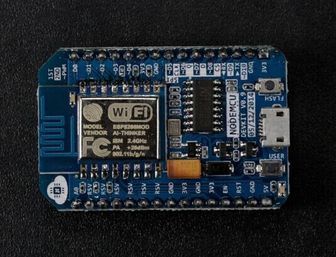
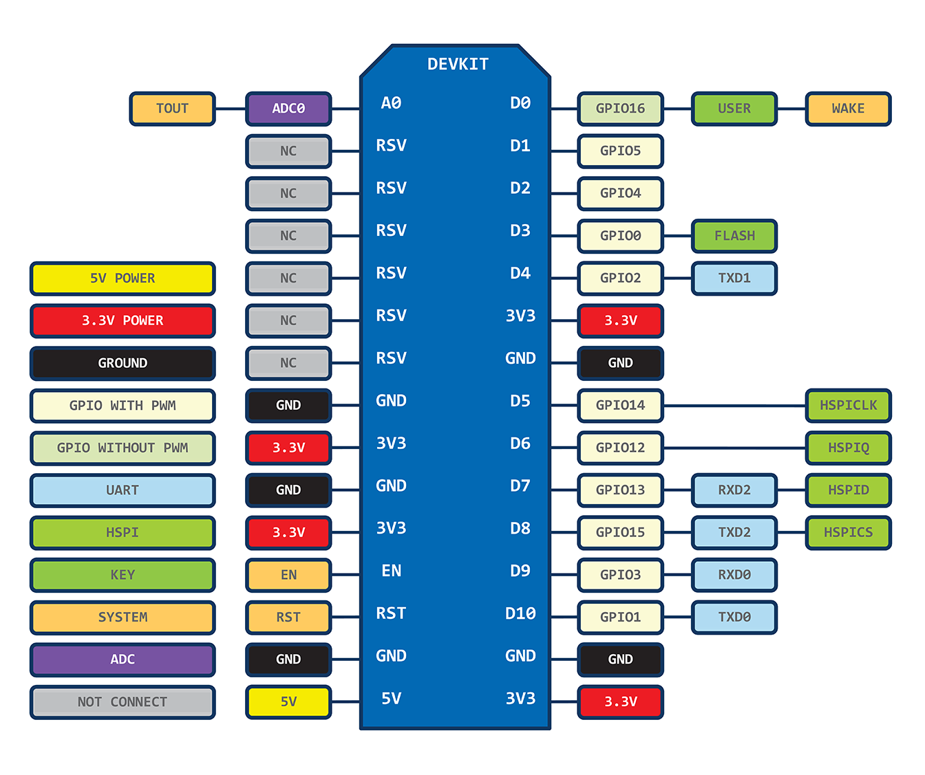
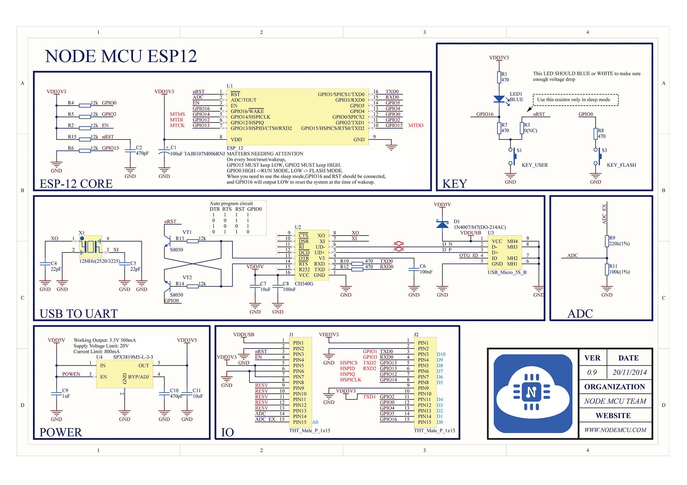
Devkit 1.0 : ESP-12E + CP2102
https://raw.githubusercontent.com/nodemcu/nodemcu-devkit/master/Documents/NODEMCU_DEVKIT_SCH.png
node.key : --deprecated
node.led : --deprecated
node.readvdd33 : --deprecated, moved to adc.readvdd33()
node.dsleep()
描述
进入睡眠模式,计时时间之后唤醒
语法
node.dsleep(us)
-注意: 如需使用此功能,需要将esp8266的PIN32(RST)和PIN8(XPD_DCDC)短接。
-注意: 如需使用此功能,需要将esp8266的PIN32(RST)和PIN8(XPD_DCDC)短接。
NodeMCU固件- i2C/SPI/Uart/1-wire控制
參考連結: NodeMCU API指令
https://github.com/nodemcu/nodemcu-firmware/tree/84a9ab35a8eb9b4ae2229bba7b2626c2a285818d/app/driver
I2C
    id=0
    sda=1
    scl=2

    -- initialize i2c, set pin1 as sda, set pin2 as scl
    i2c.setup(id,sda,scl,i2c.SLOW)

    -- user defined function: read from reg_addr content of dev_addr
    function read_reg(dev_addr, reg_addr)
      i2c.start(id)
      i2c.address(id, dev_addr ,i2c.TRANSMITTER)
      i2c.write(id,reg_addr)
      i2c.stop(id)
      i2c.start(id)
      i2c.address(id, dev_addr,i2c.RECEIVER)
      c=i2c.read(id,1)
      i2c.stop(id)
      return c
    end

    -- get content of register 0xAA of device 0x77
    reg = read_reg(0x77, 0xAA)
    print(string.byte(reg))
UART
    -- when 4 chars is received.
    uart.on("data", 4,
      function(data)
        print("receive from uart:", data)
        if data=="quit" then
          uart.on("data")
        end
    end, 0)
    -- when '\r' is received.
    uart.on("data", "\r",
      function(data)
        print("receive from uart:", data)
        if data=="quit\r" then
          uart.on("data")
        end
    end, 0)
1-Wire
-- 18b20 Example
pin = 9
ow.setup(pin)
count = 0
repeat
  count = count + 1
  addr = ow.reset_search(pin)
  addr = ow.search(pin)
  tmr.wdclr()
until((addr ~= nil) or (count > 100))
if (addr == nil) then
  print("No more addresses.")
else
  print(addr:byte(1,8))
  crc = ow.crc8(string.sub(addr,1,7))
  if (crc == addr:byte(8)) then
    if ((addr:byte(1) == 0x10) or (addr:byte(1) == 0x28)) then
      print("Device is a DS18S20 family device.")
        repeat
          ow.reset(pin)
          ow.select(pin, addr)
          ow.write(pin, 0x44, 1)
          tmr.delay(1000000)
          present = ow.reset(pin)
          ow.select(pin, addr)
          ow.write(pin,0xBE,1)
          print("P="..present)
          data = nil
          data = string.char(ow.read(pin))
          for i = 1, 8 do
            data = data .. string.char(ow.read(pin))
          end
          print(data:byte(1,9))
          crc = ow.crc8(string.sub(data,1,8))
          print("CRC="..crc)
          if (crc == data:byte(9)) then
             t = (data:byte(1) + data:byte(2) * 256) * 625
             t1 = t / 10000
             t2 = t % 10000
             print("Temperature="..t1.."."..t2.."Centigrade")
          end
          tmr.wdclr()
        until false
    else
      print("Device family is not recognized.")
    end
  else
    print("CRC is not valid!")
  end
end
SPI
id: spi id number.
mode: MASTER or SLAVE(not supported yet).
cpol: CPOL_LOW or CPOL_HIGH, clock polarity.
cpha: CPHA_HIGH or CPHA_LOW, clock phase.
databits: DATABITS_8 or DATABITS_16.
clock: spi clock (not supported yet).
id: spi id number.
mode: MASTER or SLAVE(not supported yet).
cpol: CPOL_LOW or CPOL_HIGH, clock polarity.
cpha: CPHA_HIGH or CPHA_LOW, clock phase.
databits: DATABITS_8 or DATABITS_16.
clock: spi clock (not supported yet).
2015年3月31日 星期二
NodeMCU固件-GPIO/ADC/PWM控制
參考連結: NodeMCU API指令
包括有下列Module:
node
file
wifi
wifi.sta
wifi.ap
timer
gpio
pwm
net
net server
net socket
i2c
adc
uart
1-wire
bit
spi
mqtt
mqtt client
NodeMCU 的 GPIO Pin 對應 ESP8266 GPIO Pin看連結說明.

NodeMCU 的 GPIO Module定義了12個GPIO Pin,對應如下:
GPIO16=0
GPIO5=1
GPIO4=2
GPIO0=3
關於GPIO Module說明
範例: (Pin index=0~12)
>gpio.mode(4, gpio.OUTPUT)
>gpio.write(4, gpio.LOW) --點亮GPIO2 LED
>print(gpio.read(4))
0
>gpio.write(4,gpio.HIGH) --關掉GPIO2 LED
>print(gpio.read(4))
1
>
關於ADC Module說明
測試板ADC是接光敏電阻,越暗,阻值越大,電壓越大,所讀ADC數值就會越大
範例:
>print(adc.read(0)) --暗
256
>print(adc.read(0)) --亮
0
讀Vdd33電壓
>print(adc.readvdd33()/1000) --read vdd voltage
2.944
關於PWM Module說明
Only 3 pins can be set to PWM mode at the most.
pin: 1~12, IO index
duty: 0~1023, pwm duty cycle, max 1023(10bit).
範例:
node
file
wifi
wifi.sta
wifi.ap
timer
gpio
pwm
net
net server
net socket
i2c
adc
uart
1-wire
bit
spi
mqtt
mqtt client
NodeMCU 的 GPIO Pin 對應 ESP8266 GPIO Pin看連結說明.
NodeMCU 的 GPIO Module定義了12個GPIO Pin,對應如下:
| IO index | ESP8266 pin | IO index | ESP8266 pin |
|---|---|---|---|
| 0 [*] | GPIO16 | 7 | GPIO13 (Color Blue) |
| 1 | GPIO5 | 8 | GPIO15 (Color Red) |
| 2 | GPIO4 | 9 | GPIO3 |
| 3 | GPIO0 | 10 | GPIO1 |
| 4 | GPIO2 | 11 | GPIO9 |
| 5 | GPIO14 | 12 | GPIO10 |
| 6 | GPIO12(Color Green) |
** [] D0(GPIO16) can only be used as gpio read/write. no interrupt supported. no pwm/i2c/ow supported. *
GPIO16=0
GPIO5=1
GPIO4=2
GPIO0=3
GPIO2=4
GPIO14=5
GPIO14=5
GPIO12=6
GPIO13=7
GPIO15=8
GPIO3=9
GPIO13=7
GPIO15=8
GPIO3=9
GPIO1=10
GPIO9=11
GPIO9=11
GPIO10=12
//亮Red ,暗Green,暗Blue
gpio.mode(GPIO15, gpio.OUTPUT) gpio.write(GPIO15,1) -- Red on
gpio.mode(GPIO12, gpio.OUTPUT) gpio.write(GPIO12,0) -- Green off
gpio.mode(GPIO13, gpio.OUTPUT) gpio.write(GPIO13,0) -- Blue off
關於GPIO Module說明
範例: (Pin index=0~12)
>gpio.mode(4, gpio.OUTPUT)
>gpio.write(4, gpio.LOW) --點亮GPIO2 LED
>print(gpio.read(4))
0
>gpio.write(4,gpio.HIGH) --關掉GPIO2 LED
>print(gpio.read(4))
1
>
關於ADC Module說明
測試板ADC是接光敏電阻,越暗,阻值越大,電壓越大,所讀ADC數值就會越大
範例:
256
>print(adc.read(0)) --亮
0
讀Vdd33電壓
>print(adc.readvdd33()/1000) --read vdd voltage
2.944
關於PWM Module說明
Only 3 pins can be set to PWM mode at the most.
pin: 1~12, IO index
duty: 0~1023, pwm duty cycle, max 1023(10bit).
範例:
    -- D6 is connected to green led (ESP8266 GPIO15)
    -- D7 is connected to blue led (ESP8266 GPIO12)
    -- D8 is connected to red led (ESSP8266 GPIO13)
    pwm.setup(6,500,512)
    pwm.setup(7,500,512)
    pwm.setup(8,500,512)
    pwm.start(6)
    pwm.start(7)
    pwm.start(8)
    function led(r,g,b)
      pwm.setduty(6,g)
      pwm.setduty(7,b)
      pwm.setduty(8,r)
    end
    led(512,0,0) --  set led to red
    led(0,0,512) -- set led to blue.
燒錄NodeMCU固件-安信可ESP-12測試板
有關 NodeMCU 的相關連結如下:
官網: http://nidemcu.com/
Popular repositories
最新NodeMCU最新固件下載位址:
https://github.com/nodemcu/nodemcu-firmware/releases
20150901補充 : 有float及 integer兩種版本binary... (keyword : LUA_NUMBER_INTEGRAL)
integer vs float version : integer version only support integer as lua number (less memory usage)
Numbers - Lua
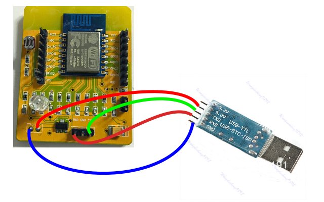
針對Windows用戶的NodeMCU Firmware燒錄步驟:
1.將GPIO0 拉LOW(將短路帽接上) ,執行NodeMCU Flasher ( Win32 , Win64)程式,接著設定正確的Com Port ,並按下"Flash" Button.
2.等候片刻
3.顯示現在的Firmware Mac Address 設定
4.此時,可設定你想燒錄的檔案.
20150908補充:燒錄時請儘量連接至電腦的USB Port,就是不經過其他Hub,若使用由外部USB Hub接出的Port,會有無法燒錄或燒錄失敗的可能....
燒錄完成後記得GPIO0回復為High(Normal mode),
Baud Rate設成9600 , Reset and reboot 後,會看到如下輸出......
燒錄完成後記得GPIO0回復為High(Normal mode),
Baud Rate設成9600 , Reset and reboot 後,會看到如下輸出......


訂閱:
文章 (Atom)